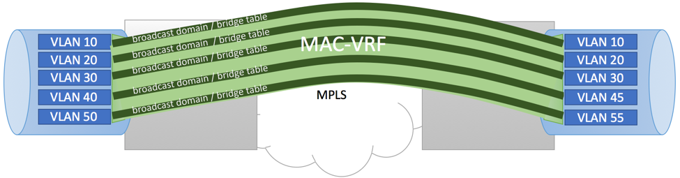
In this article, we will review EVPN MPLS Port-Based VLAN-Aware Bundle Service configuration example using Juniper MX devices. As per Port-Based VLAN-Aware service definition in RFC7432, all of the VLANs on the port are part of the same service and are mapped to a single bundle without any VID translation.
In our sample, we will add L3 IRB interfaces to VLANs, simulating L3 Default Gateways.
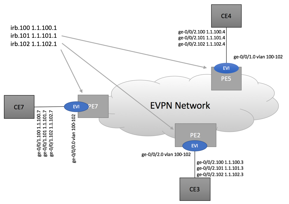
Our lab topology is shown below:
PE Configuration
Example below shows configuration element that are directly related to EVPN service being provided on PE2. Please refer to our GitHub repository for complete configurations.
CE-Facing Interface Configuration
Configure Physical Interface as family ‘bridge’ permitting desired VLANs:
ge-0/0/1 {
        unit 0 {
            family bridge {
                interface-mode trunk;
                vlan-id-list 100-102;
            }
        }
    }
Configure IRB Interface as needed:
    irb {
        unit 100 {
            family inet {
                address 1.1.100.1/24;
            }
            mac 00:00:5e:01:00:00;
        }
        unit 101 {
            family inet {
                address 1.1.101.1/24;
            }
            mac 00:00:5e:01:01:00;
        }

        unit 102 {
            family inet {
                address 1.1.102.1/24;
            }
            mac 00:00:5e:01:02:00;
        }
}
Configure Virtual Switch and allow protocol EVPN
routing-instances {
    CUSTOMER-A {
        instance-type virtual-switch;
        interface ge-0/0/1.0;
        route-distinguisher 120.0.2.2:1;
        vrf-target target:100:1;
        protocols {
            evpn {
                extended-vlan-list 100-102;
                default-gateway do-not-advertise;
            }
        }

        bridge-domains {
            BD100 {
                vlan-id 100;
                routing-interface irb.100;
            }

            BD101 {
                vlan-id 101;
                routing-interface irb.101;
            }

            BD102 {
                vlan-id 102;
                routing-interface irb.102;
            }
        }
    }
Configure L3 VRF
In our example, we are configuring individual VRF per IRB. Depending on your use case, you might want to leverage single L3 VRF for all IRB interfaces of a given customer.
    CUSTOMER-A-L3-IRB100 {
        instance-type vrf;
        interface irb.100;
        route-distinguisher 120.0.2.2:100;
        vrf-target target:100:100;
        vrf-table-label;
        protocols {
            evpn {
                ip-prefix-routes {
                    advertise direct-nexthop;
                }
            }
        }
    }

    CUSTOMER-A-L3-IRB101 {
        instance-type vrf;
        interface irb.101;
        route-distinguisher 120.0.2.2:101;
        vrf-target target:100:101;
        vrf-table-label;
        protocols {
            evpn {
                ip-prefix-routes {
                    advertise direct-nexthop;
                }
            }
        }
    }

    CUSTOMER-A-L3-IRB102 {
        instance-type vrf;
        interface irb.102;
        route-distinguisher 120.0.2.2:102;
        vrf-target target:100:102;
        vrf-table-label;
        protocols {
            evpn {
                ip-prefix-routes {
                    advertise direct-nexthop;
                }
            }
        }
    }
}
Service Validation
If everything works as expected, you should be able to achieve end-to-end connectivity between corresponding VLANs. From CE7, we are able to ping VLAN 100, 101 and 102 of CE3 and CE4.
bgphelp@CE3-Downstream3> ping 1.1.100.4
...
3 packets transmitted, 3 packets received, 0% packet loss


bgphelp@CE3-Downstream3> ping 1.1.100.7
...
3 packets transmitted, 3 packets received, 0% packet loss

…


bgphelp@CE3-Downstream3> ping 1.1.102.7
...
3 packets transmitted, 3 packets received, 0% packet loss
Control Plane Information
Please note that the same MPLS Label ID is used for all three VLANs originated by a given PE:
root@PE7> show route table CUSTOMER-A.evpn.0


CUSTOMER-A.evpn.0: 21 destinations, 21 routes (21 active, 0 holddown, 0 hidden)

+ = Active Route, - = Last Active, * = Both

…

2:120.0.2.5:1::100::00:0c:29:82:c2:a9/304 MAC/IP
                   *[BGP/170] 05:33:04, localpref 100, from 120.0.2.5
                      AS path: I, validation-state: unverified
                    > to 120.0.3.32 via ge-0/0/1.570, Push 800205

2:120.0.2.5:1::101::00:0c:29:82:c2:a9/304 MAC/IP
                   *[BGP/170] 05:33:04, localpref 100, from 120.0.2.5
                      AS path: I, validation-state: unverified
                    > to 120.0.3.32 via ge-0/0/1.570, Push 800205

2:120.0.2.5:1::102::00:0c:29:82:c2:a9/304 MAC/IP
                   *[BGP/170] 05:33:04, localpref 100, from 120.0.2.5
                      AS path: I, validation-state: unverified
                    > to 120.0.3.32 via ge-0/0/1.570, Push 800205
Wireshark captures showing CE-to-CE and broadcast traffic can be downloaded here. Captures were take on PE7’s MPLS Network-facing port.
Additional control plane information:
root@PE7> show evpn instance CUSTOMER-A extensive

Instance: CUSTOMER-A
  Route Distinguisher: 120.0.2.7:1
  Per-instance MAC route label: 299872
  MAC database status                     Local  Remote
    MAC advertisements:                       6       6
    MAC+IP advertisements:                    5       4
    Default gateway MAC advertisements:       3       0
  Number of local interfaces: 1 (1 up)
    Interface name  ESI                            Mode             Status     AC-Role
    ge-0/0/0.0      00:00:00:00:00:00:00:00:00:00  single-homed     Up         Root

  Number of IRB interfaces: 3 (3 up)
    Interface name  VLAN   VNI    Status  L3 context
    irb.100         100            Up     CUSTOMER-A-L3-IRB100
    irb.101         101            Up     CUSTOMER-A-L3-IRB101
    irb.102         102            Up     CUSTOMER-A-L3-IRB102

  Number of bridge domains: 3
    VLAN  Domain ID   Intfs / up    IRB intf   Mode             MAC sync  IM route label
    100                  1    1     irb.100    Extended         Enabled   300032
    101                  1    1     irb.101    Extended         Enabled   300048
    102                  1    1     irb.102    Extended         Enabled   300064

  Number of neighbors: 2
    Address               MAC    MAC+IP        AD        IM        ES Leaf-label
    120.0.2.2               3         1         0         3         0
    120.0.2.5               3         3         0         3         0

  Number of ethernet segments: 0


root@PE7> show evpn database

Instance: CUSTOMER-A

VLAN  DomainId  MAC address        Active source                  Timestamp        IP address
100             00:00:5e:01:00:00  irb.100                        May 04 13:49:41  1.1.100.1
100             00:0c:29:31:01:ed  ge-0/0/0.0                     May 04 19:14:50  1.1.100.7
100             00:0c:29:82:c2:a9  120.0.2.5                      May 04 13:49:40  1.1.100.4
100             00:0c:29:de:e3:64  120.0.2.2                      May 04 19:16:22  1.1.100.3
101             00:00:5e:01:01:00  irb.101                        May 04 14:05:25  1.1.101.1
101             00:0c:29:31:01:ed  ge-0/0/0.0                     May 04 19:16:45  1.1.101.7
101             00:0c:29:82:c2:a9  120.0.2.5                      May 04 13:49:40  1.1.101.4
101             00:0c:29:de:e3:64  120.0.2.2                      May 04 19:17:01
102             00:00:5e:01:02:00  irb.102                        May 04 14:05:25  1.1.102.1
102             00:0c:29:31:01:ed  ge-0/0/0.0                     May 04 19:17:15
102             00:0c:29:82:c2:a9  120.0.2.5                      May 04 13:49:40  1.1.102.4
102             00:0c:29:de:e3:64  120.0.2.2                      May 04 19:17:11
Thanks. Very nice article. Much easier to understand rfc after reading this.
Can you please explain how vlan-aware bundle works?
And How VID translation is happened?
what is normaliZed Ethernet tag in rfc 7432?
Please explain with some example. RFC is very confusing.