Configuring Dual-CE BGP High Availability Site. This article provides Juniper Configuration Example that uses BGP AS-Prepend to identify primary and secondary paths.
Continue reading “Juniper High Availability Customer Site using AS-Prepend”
Tag: Multihoming
BGP for Enterprise Networks
BGP High Availability and Multihoming scenarios for Enterprise customers. Single ISP and Multi-ISP Redundancy.
Introduction
In this article, we will focus on building reliable Internet access to Enterprise branches. We will discuss single- and multi-homing scenarios and how BGP protocol can be leveraged in these deployments. While IPv4-based examples will be provided, this paper is also applicable to IPv6 deployment scenarios. The focus of this paper is Internet connectivity, although discussed techniques can be used for other types of connectivity, such as private IP VPN.
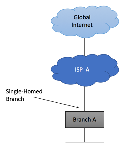
Single-homed network
As the name suggests, single-homed network is the network with just one external link. This is the type of Internet connectivity you have at home and the most common implementation scenario for small branch locations. It is simple, inexpensive and readily available. Your service provider might allocate a single IP address to the branch, requiring you to do NAT on border device, or might give you a large block allowing to assign Internet-reachable IP addresses to all branch devices.
If you were allocated only one IP address that is configured on ISP-facing interface of your border router, all you need to
- Setup default route pointing towards ISP’s network
- Select RFC1918 prefix that will be used to address your LAN infrastructure
- Configure NAT
If ISP did provide you with a large Internet-routable block, you should come to an agreement on how this block will be advertised to the Internet.
The most common scenario is the static configuration on ISP’s edge router to point to your device. For example, branch A was assigned 128.66.1.0/24 prefix.
ISP will do two things:
- Configure Static Route for 128.66.1.0/24 pointing to your Customer Premises Equipment (CPE) router
- Redistribute this static route into one of dynamic routing protocols, making the rest of ISP A’s infrastructure aware of the network that was assigned to you
On your end, you will configure default 0.0.0.0/0 route to point to ISP A’s router, and assign given 128.66.1.0/24 network to CPE’s branch-facing interface.
Even in a single-homed scenario, it is possible to use dynamic routing protocols to advertise 128.66.1.0/24 prefix and accept default route from the ISP, although there is no technical benefit in doing this.
As your company grows, you might have additional offices to connect to the Internet. If these offices are connected in a similar fashion, you will still be using “Single-Homed” implementation.
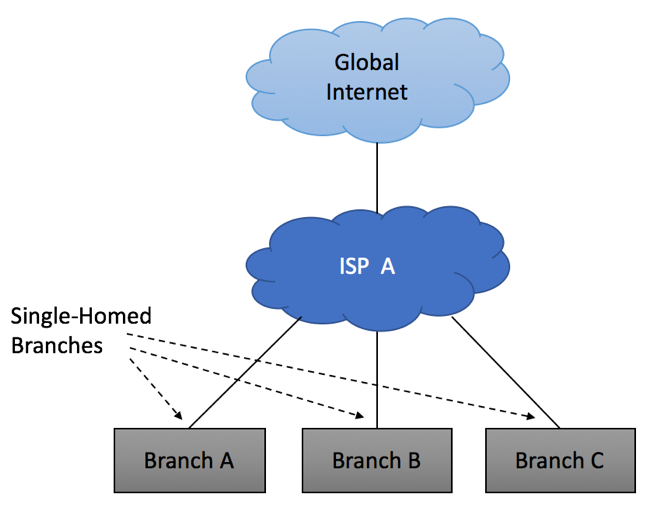
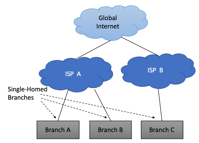
It is not uncommon to use different Service Providers to connect different branches, yet all your connections will still be “Single-Homed.”
Multi-Homing Overview
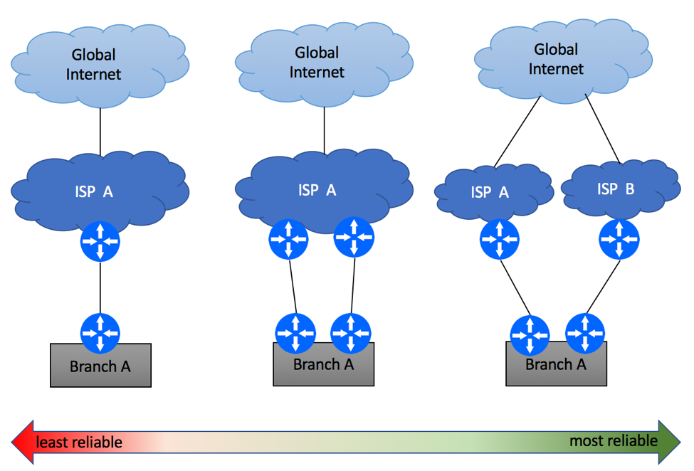
Assuming Internet connectivity is critical to your business, having a single link between ISP and your offices is a recipe for disaster. Equipment failure, fiber cuts, maintenance windows and DDoS attacks are common sources of Internet outages. In order to protect yourself, you should consider Internet multi-homing, where your branches will have an alternate path to the Internet in case of the primary link failure. While many Service Providers will be happy to sell you “redundant” Internet connectivity, it is important to understand that there are many levels of redundancy. Diagram below shows some examples, starting with the least reliable option of the secondary circuit being terminated on the same routers, and all the way to dual-homing scenario where your branch is connected to two ISP’s via two fully redundant paths.
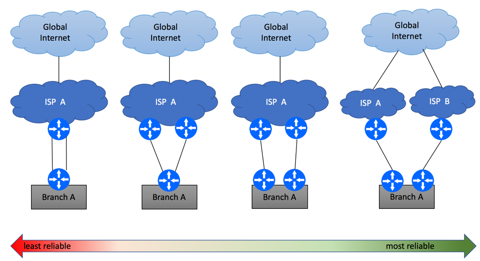
Multi-Homing Scenario 1 – Same PE / CE
The simplest and the least reliable multi-homing scenario is where two physical links are terminated on the same Layer 3 devices on both ends. Depending on ISP’s capabilities, this service might be delivered over the same (e.g. two T1 circuits) or different access (e.g. DSL and LTE) media technologies. While it is recommended to avoid this type of setups if high availability is your primary concern, this might be the only option in some geographical areas.
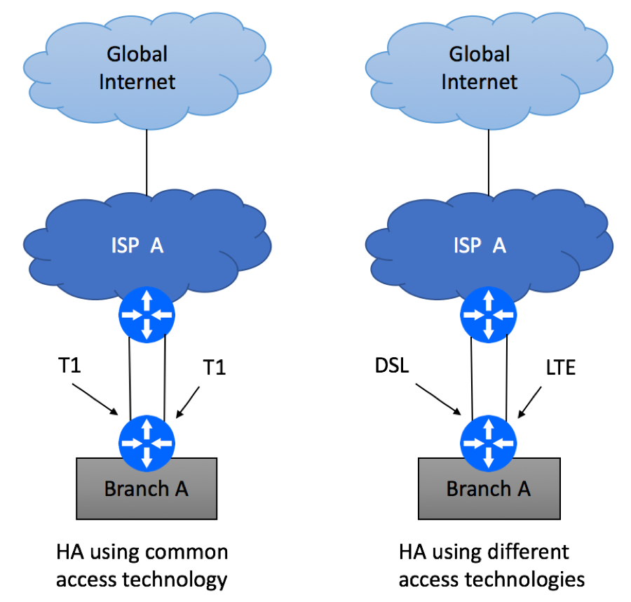
Branch device configuration will be dictated by ISP’s service offerings and might include the following options
- For common access technology, ISP might offer transport bonding, where one L3 paths is created from multiple physical links. This might be called T1 bonding, Ethernet Port Channel, Ethernet Link Aggregation, etc.
- In case of dissimilar technologies, two L3 paths will be created. Most commonly, these two paths will be configured in Active / Standby mode, where the primary path takes all the traffic until it is declared unusable. Then the traffic will switch over to the secondary path. Failure detection mechanisms will vary from ISP to ISP and might include L2 OAM, BFD, L3 routing.
While BGP protocol can be used for failure detection and load-balancing in single PE / single CE scenario, it provides limited benefit to you as the end user.
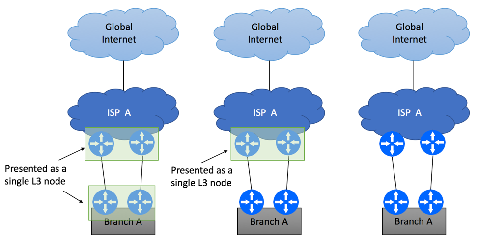
Multi-Homing Scenario 2 – Different PEs / Single CE
The second common scenario is the one where branch’s Internet circuits are terminated on two PE devices as shown below, while you continue to utilize single device at the branch site.
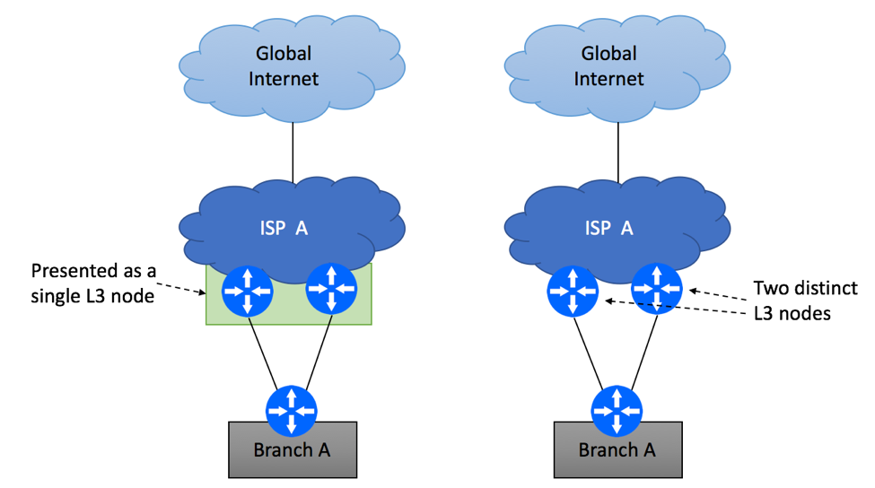
Your ISP might have the capability to join two physical devices into a single logical L3 node, meaning that the rest of the network (including CPE at your site) will see this combined system as a single router. The obvious benefit of this type of technology is improved availability of the service, as failure of one node will not cause an outage for dual-homed customers. There are also some known drawbacks, for example software bug or configuration mistake is likely to impact both ISP’s nodes at the same time.
The second scenario is the one where two PE devices are completely independent of each other. Most likely, this will mean that one of the physical paths will be designated as “primary” and the second as “secondary.” Both static routing and BGP are commonly used for these deployments, so let’s review both cases.
If you opt out to use static routing, ISP will configure static routes on their primary and secondary PE devices pointing to your CPE as shown below. They will then redistribute these routes into their routing protocol of choice, such as IBGP.
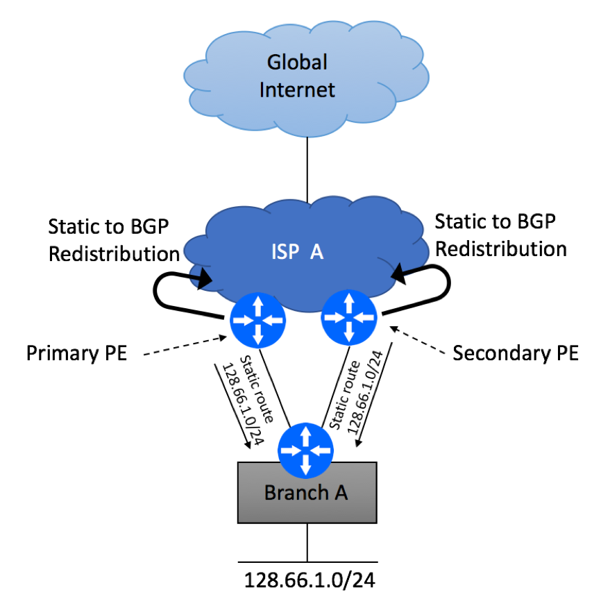
ISP will also need to make sure that there is a reliable mechanism in place to detect link failure condition between your branch CPE and PE router. BFD is a popular option, although not all platforms can support it.
On the CPE side, you’ll need to configure two static routes pointing to the primary and the secondary PE devices. You have a choice of configuring these two routes with the same metric (admin distance in Cisco’s terms) or different metrics. If both of your paths have the same characteristics (bandwidth and latency), configuring equal metrics is a viable option. If your paths are not the same, for example 10Mb Ethernet as primary and T1 as secondary, configuring the primary one with lower metric and the secondary one with higher metric would make more sense.
If you decide to use BGP instead of the static routing, you’ll need to do a few things:
- Request Private BGP Autonomous System (AS) Number from your ISP, unless you have a public AS assigned to you by the Regional Internet Registry
- Find out what BGP AS is being used by your Service Provider
- Agree on MD5 keys to use for your EBGP sessions
- Ask your ISP to advertise default-route only. There is no need for you to get the full BGP view, too many routes might overwhelm your CPE device.
- Ask what communities are supported by your ISP to identify the primary and the secondary paths
- Advertise the prefix that was assigned to you with corresponding communities
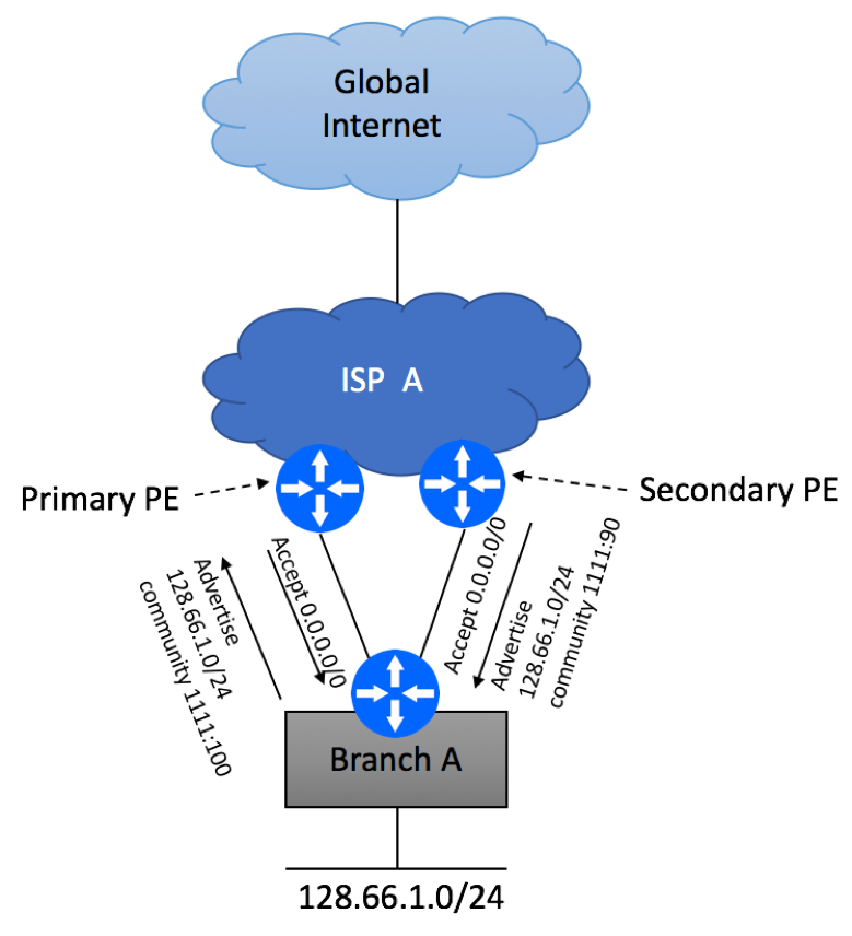
Let’s assume that your ISP supports the following communities:
- 1111:100 – primary Internet path
- 1111:90 – secondary Internet path
Configure BGP sessions as shown below. Make sure you only advertise the prefix assigned to you by the ISP and not your internal routes.
Multi-Homing Scenario 3 – Different PEs and CEs
The third scenario requires physical router redundancy on both Service Provider’s and Customer’s sites. There are a few deployment options to be considered.
Analogous to how Service Provider might combine two physical nodes to work as a single L3 device, you can employ similar technique on your end. This can be done by leveraging proprietary vendor implementations, such as Virtual Switching Systems, Virtual Chassis, firewall clusters, etc. If you take this route, you will effectively create a single L3 node, so configuration techniques discussed in “Scenario 2” section would be applicable to this use case.
If two CPE’s are not combined, you will need to rely on routing protocols to forward traffic to and from the Internet. Both static routing and BGP can still be used in a dual-CPE deployment. Let’s discuss static routing deployment first.
With static routing, your Service Provider will configure static routing and routing redistribution the same way they’d have configured it in a single-CPE scenario, but configuration of the CPE device at the customer site will be more complex.
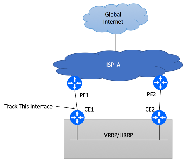
- On both CE1 and CE2 devices, configure static default routes pointing to corresponding PE devices
- Decide which CPE device will be used as the primary router for Internet connectivity
- Configure either VRRP or HSRP between your CPE devices. Primary device should have higher VRRP/HSRP priority. Allow pre-emption.
- Configure upstream interface tracking and VRRP/HSRP priority change on upstream link failure.
- As an additional protection mechanism, consider enabling IP SLA to monitor the status of ISP’s PE device modifying HSRP/VRRP priority if the device becomes unreachable. This helps to avoid blackholing if CE1 is unable to detect link failure or if PE1 experiences issues while keeping interfaces in “up” state.
While static routing configuration might be preferred by some network administrators in dual-PE / dual-CPE deployment due to its simplicity, BGP-based configuration is a valid and in many cases preferred alternative.
To get BGP going, follow these configuration steps:
- Request Private BGP Autonomous System (AS) Number from your ISP, unless you have a public AS assigned to you by the Regional Internet Registry. You will only need one AS Number as both CE devices belong to the same site.
- Find out what public AS is being used by your Service Provider
- Agree on MD5 keys to use, this will secure your EBGP session
- Ask your ISP to advertise default-route only. There is no need for you to get the full BGP view
- Ask what communities are supported by your ISP to identify the primary and the secondary paths
- Advertise the prefix that was assigned to you with corresponding communities via EBGP session
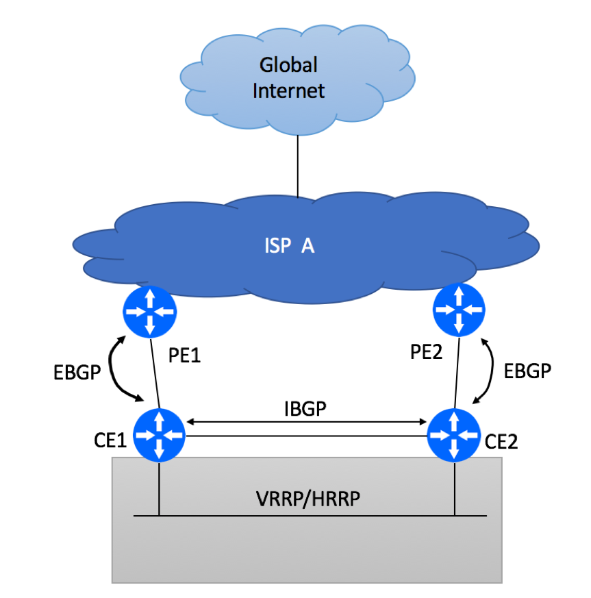
- Configure IBGP session between CE devices. The purpose of this IBGP session is to exchange the default route learned from the ISP between CE devices. Under normal conditions, this IBGP-learned route will not be used as EBGP path will be preferred. But IBGP-learned prefix will get utilized when CE-PE link failure.
- Configure VRRP between CE devices.
- Configure upstream interface tracking and VRRP/HSRP priority change on upstream link failure. Although with IBGP session in place, you will not experience traffic blackholing, VRRP failover will help you to bypass CE router with failed upstream link.
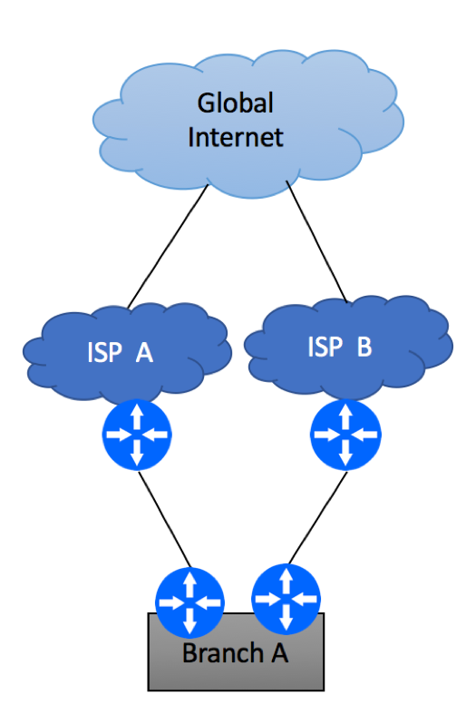
Multi-Homing Scenario 4 – Multiple ISPs
The last and the most reliable multi-homing scenario is the one where your network is connected to different service providers. As always, there are multiple flavors of this implementation.
But before we go into implementation details, ask yourself these questions:
- Are there any services hosted within your branch location that need to be reachable via the Internet? An example of these services can be VPN concentrator, Web, Mail or File Server.
- Can those services support multiple external IP addresses and take care of seamless failover if public IP changes? For example, Email server can be assigned two public IP addresses – one provided by the ISP A and the second IP provided by ISP B. Two DNS MX records pointing to these IP addresses will take care of the service failover. Other services, such as Web server, while capable of being reachable via multiple external IPs, will not perform well if one of the IP addresses goes away. DNS records will need to be updated to purge no longer reachable IP address, sessions in progress will drop and user experience will suffer.
- Can non-graceful failover be tolerated for inside-out connectivity (users in the branch trying to reach the Internet)? Is it acceptable if all user’s session will drop and users will need to reconnect to the resources they’ve used on the Internet?
If your users can accept short period of service interruption when traffic fails over from one ISP to another, and you are not hosting any mission critical Internet-facing services in your branch location, you have a simpler problem to solve. This is nothing but a single-homed network scenario we described at the very beginning of this article, repeated twice. Your service providers will allocate IP Prefixes from their respective routable IP pools, and you will have two independent IP ranges to assign to the end devices at your branch site. Most network administrators would setup a firewall cluster and configure NAT pools using IP addresses provided by the ISPs for NAT pools. As you will be configuring two default routes on your firewall cluster pointing to two different Service Providers, there will be a need to implement policy-based routing on your device to make sure traffic with a wrong source IP is not being sent. For example, you got 128.66.1.0/24 allocation from ISP A and 128.66.2.0/24 from ISP B.
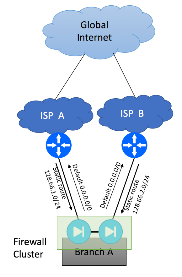
Please note that you should never try to send packets with source IP in 128.66.1.0/24 range to ISP B and packets with source IP 128.66.2.0/24 to ISP A, as ISP’s anti-spoofing mechanisms such as uRPF might drop these packets. Your policy-based routing configuration should check the source IP of the packet and send it via correct egress interface.
If the services hosted in your branch location require 100% uptime and cannot allow external IP change, you must implement BGP. You’ll need to follow the steps outlined below:
- Make sure your Internet providers can support BGP over your transport media. For example, some ISPs will allow you to run BGP over T1 and Ethernet-based links but not over DSL and 3G and LTE.
- Request Public Autonomous System (AS) number from one of the Regional Internet Registries (ARIN, RIPE, APNIC, LACNIC or AFRINIC). In order to qualify for AS, you will need to meet the following requirements: “If you are qualifying under the multihomed policy you will need to provide the exterior gateway protocol to be used, the IP addresses currently in use on your network, the AS number and name of each of your upstream providers and/or peers along with contractual verification of service with at least two of them.” Source: http://teamarin.net/2014/01/31/how-to-request-an-asn-from-arin/
- Request publicly-routable IP prefix. This might become the most difficult part of your project. Due to IPv4 depletion, it is very unlikely that you will be able to get direct allocation from one of the RIRs. This means that you will need to get routable IPv4 space from one of your ISPs, and get their permission to start BGP advertisement of this space from your own AS via a different ISP!
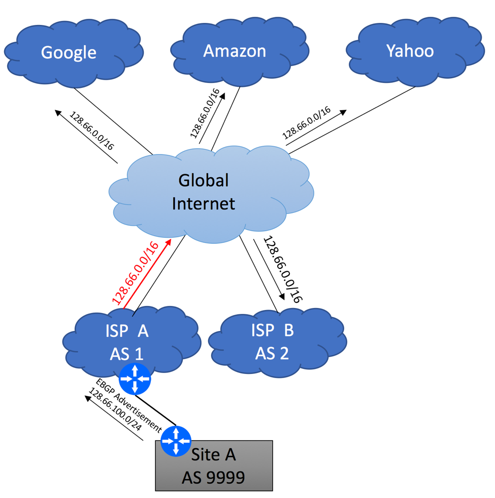
Here is an example to illustrate this scenario. Imagine, that ISP A was assigned 128.66.0.0/16 by RIPE. Being a good Internet citizen, ISP A advertises this aggregate block via BGP to the Internet, while suppressing smaller advertisements.
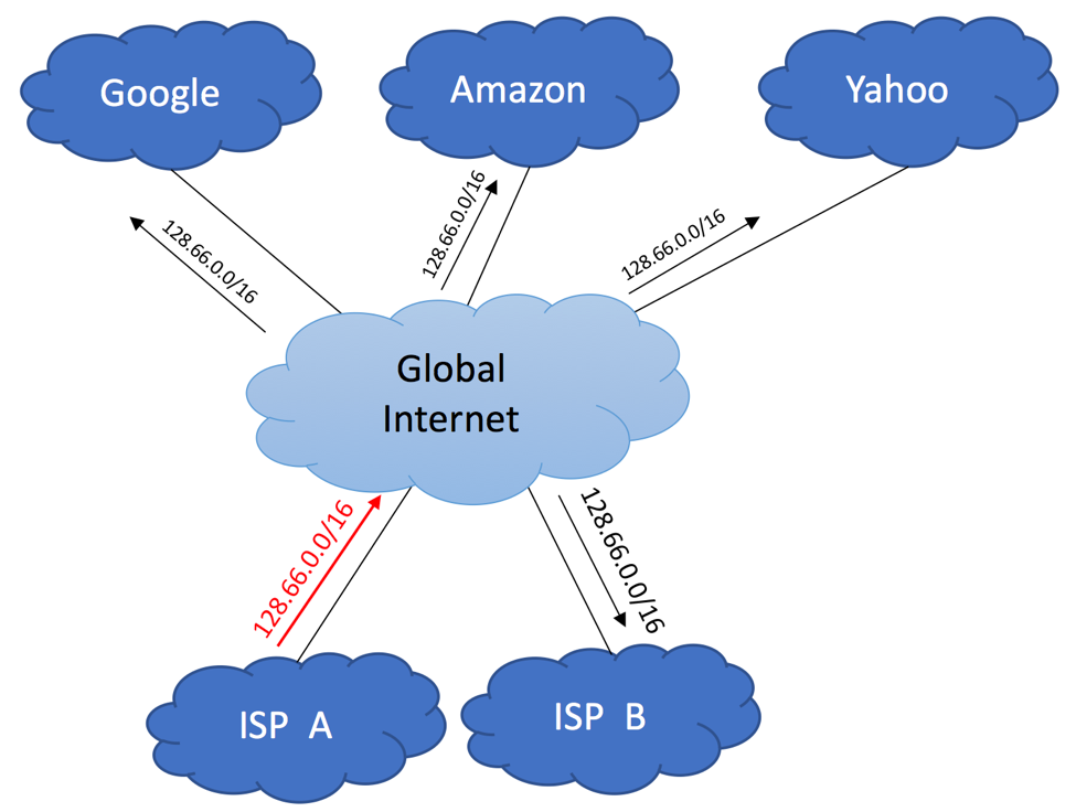
ISP B receives this advertisement as a part of the Global Routing Table update either from ISP A (assuming ISP A and ISP B maintain direct peering relationships), or via 3-rd party service provider. The same applies to all other companies that participate in the global BGP.
Now, let’s pretend that ISP A assigned 128.66.100.0/24 prefix to your Site A. Information about this 128.66.100.0/24 network would need to be propagated within ISP A’s network, so that traffic coming from the global Internet could find its way to your circuit, but specific 128.66.100.0/24 advertisement does not have to be sent to the Internet. 128.66.0.0/16 that is currently being advertised already includes 128.66.100.0/24 block, making it reachable from everywhere. More specific 128.66.100.0/24 advertisement originated from your Site A will be suppressed by ISP A and will not be leaked to the Global Internet.
It is not important if ISP A uses static routing between their PE device or rely on BGP – in order to be good internet citizens, they should suppress 128.66.100.0/24 advertisement.
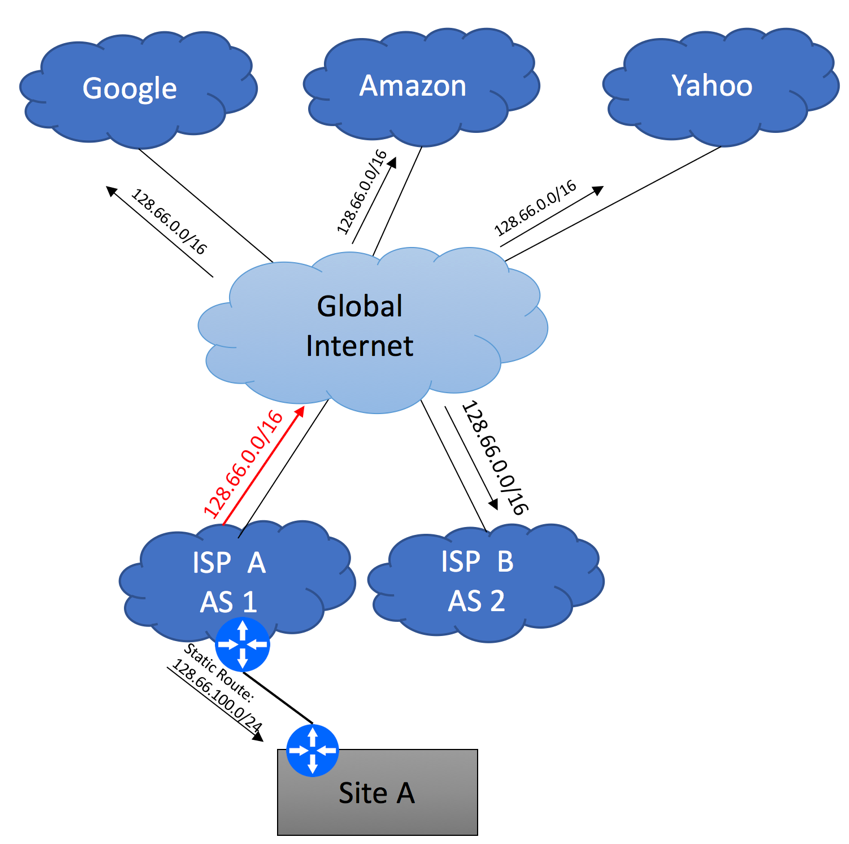
As your end goal is to start advertising 128.66.100.0/24 from your own AS, let’s review the following example, assuming that ISP A’s public AS number is 1, ISP B’s Public AS number is 2 and your company got assigned AS 9999.
In the initial state, when ISP A receives 128.66.100.0/24 advertisement originated from AS 9999 they will not propagate it to the Global Internet. This is perfectly fine, as the only way for the Internet to reach Site A is via ISP A, and ISP A already originates an aggregate 128.66.0.0/16 block. By sending your 128.66.100.0/24 to the rest of the Internet, ISP A will increase the size of Global BGP table for everybody without achieving any benefits.
Your next step is to establish EBGP peering between Site A and ISP B and advertise 128.66.100.0/24 to ISP B. You will need to get an approval from ISP A for this, and you will need to present this approval to ISP B.
As ISP B does not own 128.66.100.0/24 or any part of 128.66.0.0/16, there is no way for the to aggregate /24 prefix, so they will re-advertise your 128.66.100.0/24 prefix to the rest of the Internet. Now we observe an interesting paradox, where the global Internet starts using ISP B to send traffic to your Site A, despite the fact that 128.66.100.0/24 prefix is owned by ISP A. You can attempt to do AS prepend on your advertisements towards ISP B, but it will not make a difference, as more specific route will always win. The only traffic you might observe on your ISP A – Site A link is the traffic originated from ISP A’s direct clients.
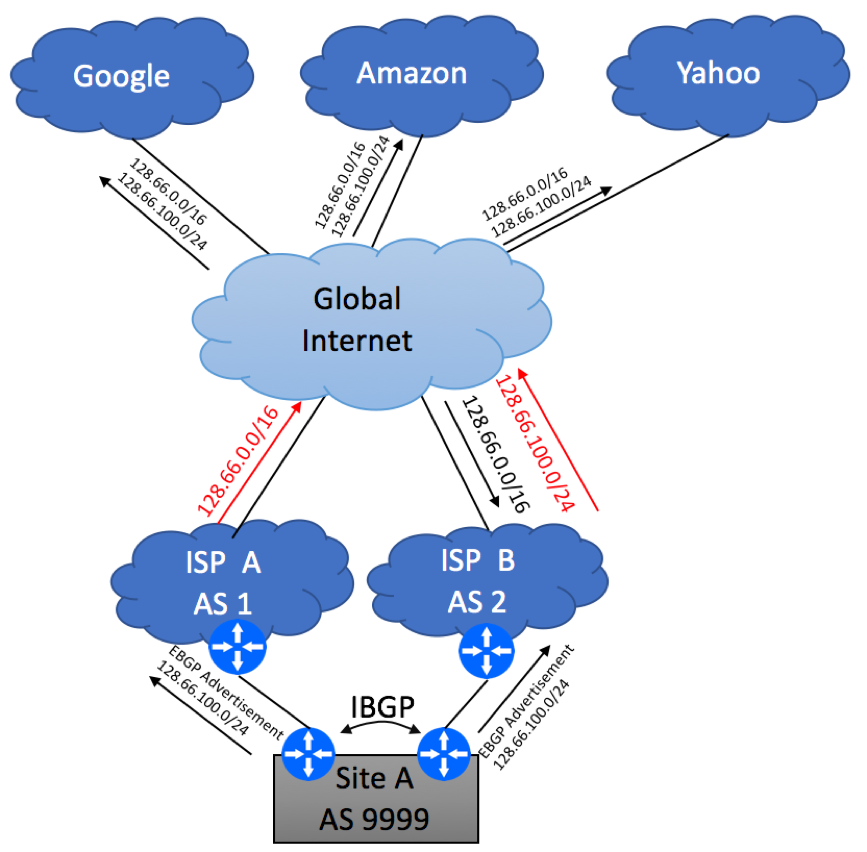
If redundancy is your only concern and ISP A is fine with the fact that the majority of your traffic is being sent via their competitor, you can stop here. Failover will work as it is. If your CE2 or CE2 to ISP B’s link goes down, or even if the entire ISP B disappears, traffic will get rerouted via ISP A thanks to the aggregate 128.66.0.0/16 block being advertised by ISP A.
If this situation is not acceptable and you due to load-balancing requirements or ISP A insists on seeing CE1 – ISP A being used under normal conditions, ISP A will have no choice but to stop suppressing your specific advertisement and start leaking 128.66.100.0/24 originated from AS 9999 to their peers. This will take care of the traffic coming to the Internet and destined to your network. It is not possible to say ahead of time what percentage of the incoming traffic will come via ISP A vs ISP B, but there will be some level of load balancing.
The next step is to figure out the best way to send the traffic from your site to the Internet. The simplest solution is to accept the default 0.0.0.0/0 route from both ISP A and ISP B. If you have a preference for the primary path, you can configure ingress BGP policy and set higher BGP local preference for the default route coming from either ISP A or ISP B. If your routers are capable of supporting the full BGP view (meaning they can handle close to 1Mln routes), you can request your ISPs to send you the full Internet routing table. Leave it to BGP to decide what path to take to reach the Internet destinations. And don’t forget to configure IBGP session between your CE devices!