Introduction
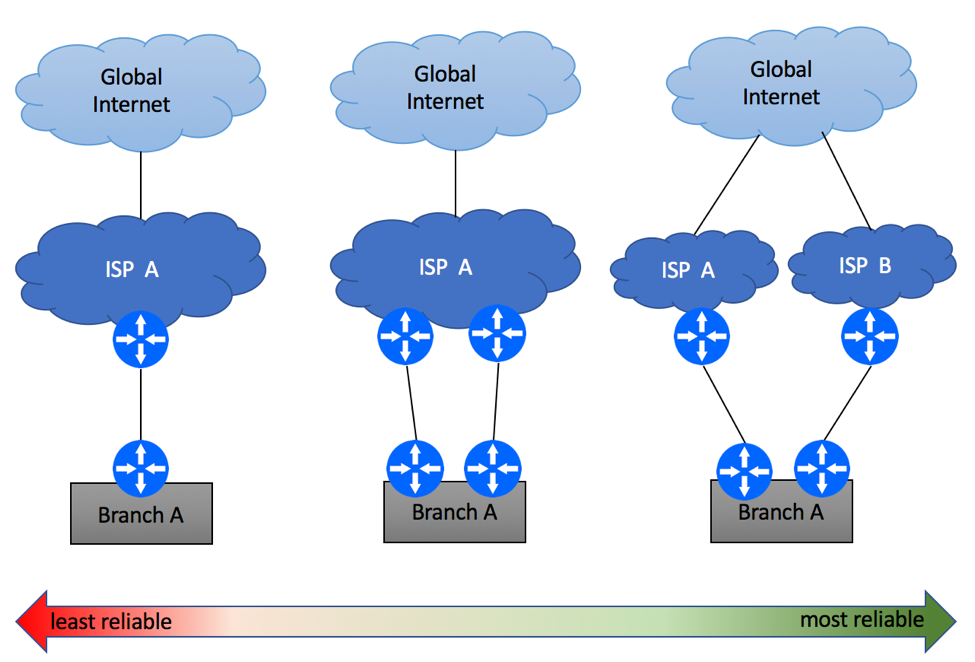
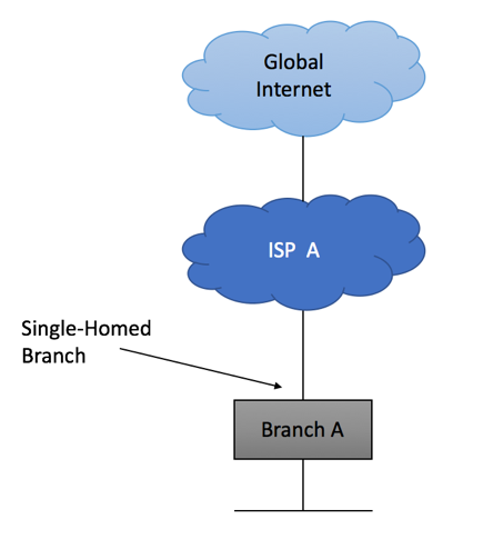
In this example, we will show recommended configuration for a Single-homed Single CE device using private AS with an upstream ISP. It is assumed that management of this device will be performed from a dedicated server residing within Customer’s Network.
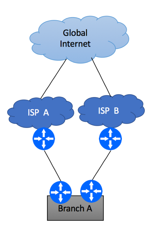
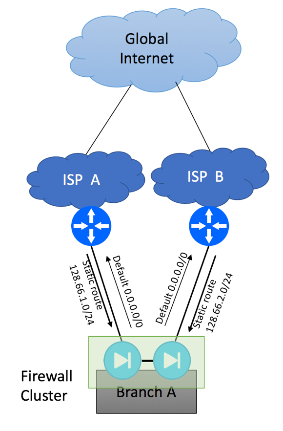
This type of setup is quite common in an environment where a dedicated firewall performing source NAT function is setup to protect customer infrastructure.
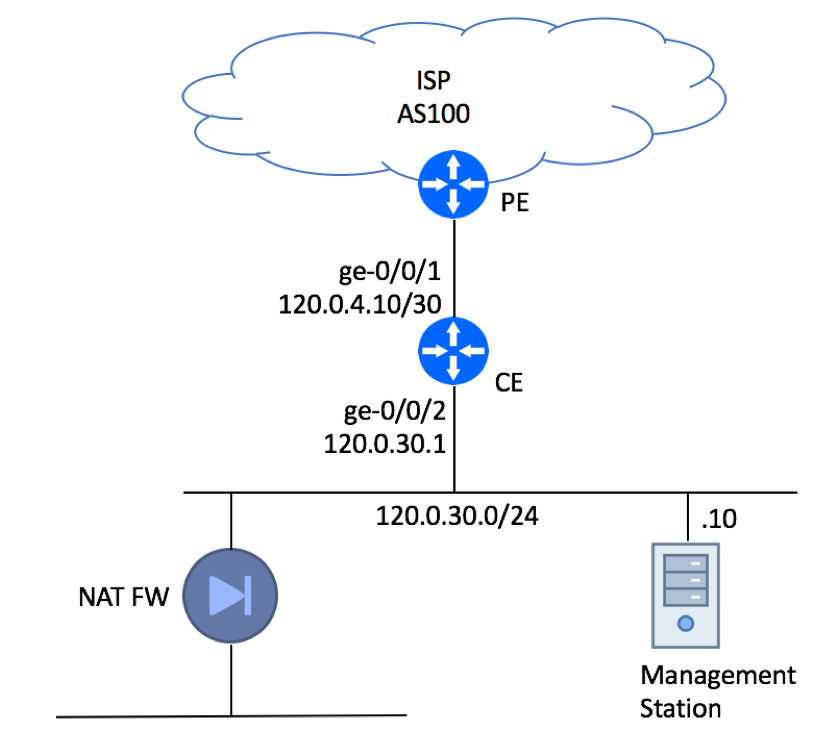
Please note, that the Management Station is connected directly to the LAN interface for illustration purpose only. In real production deployments it must be protected by a firewall.
BGP Configuration
BGP configuration can be split in the following tasks:
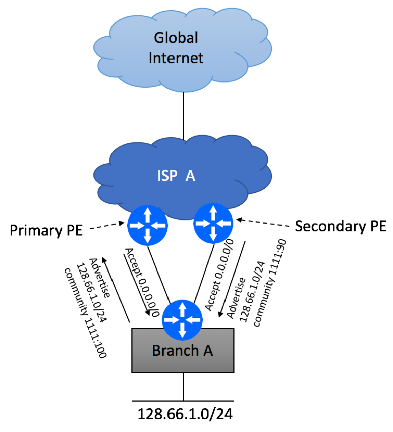
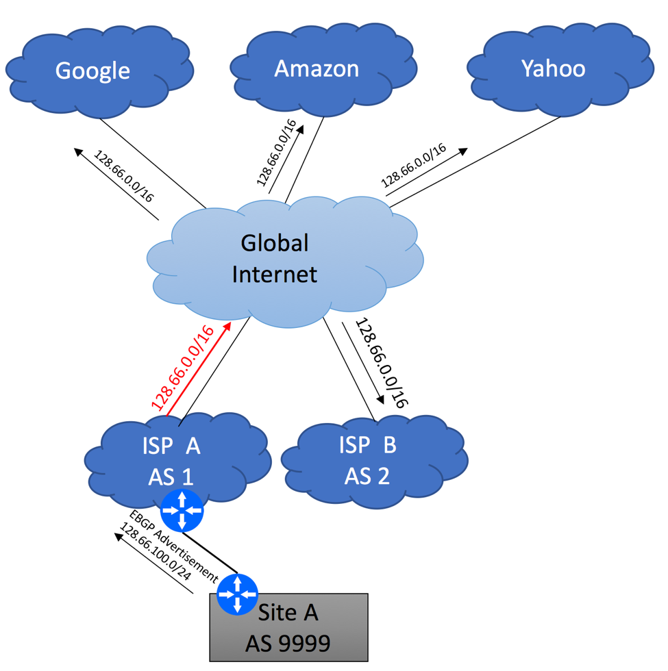
- Accept the default route from the ISP while discarding all other advertisements that might be sent to your CE
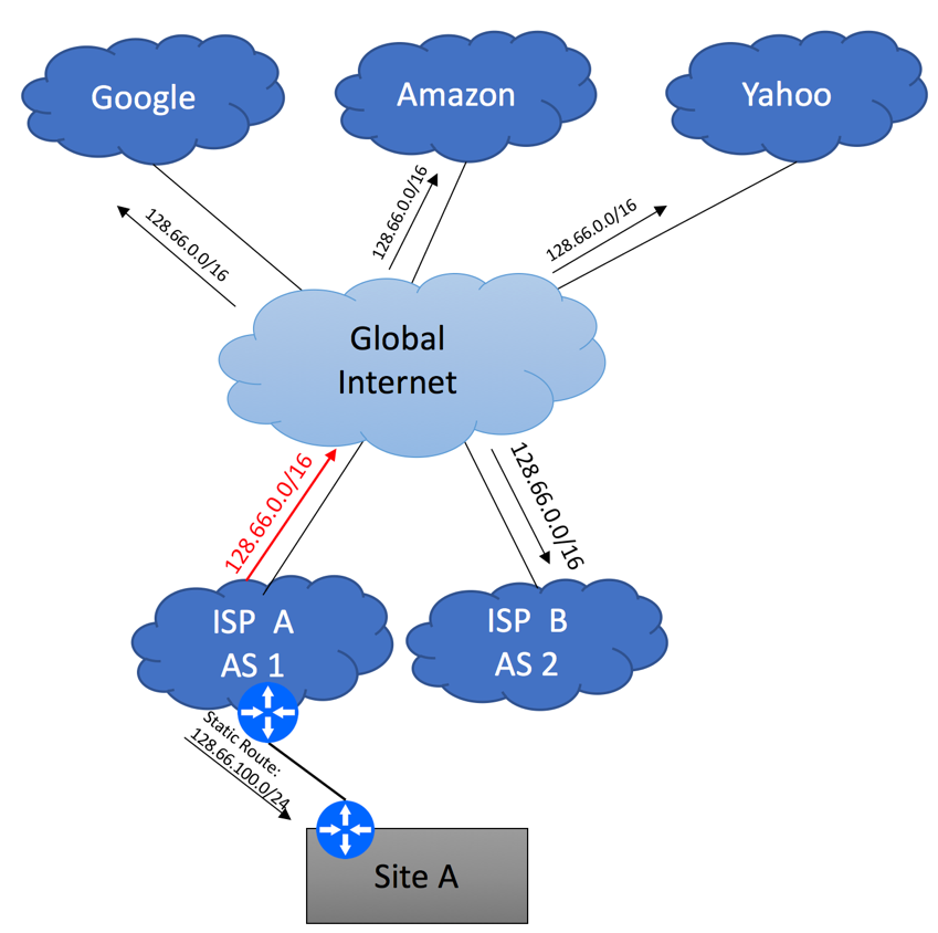
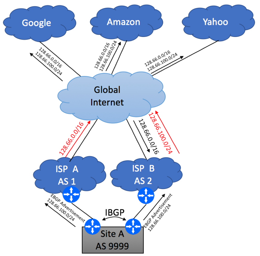
- Advertise your subnet (120.0.30.0/24) while making sure that no other routers are erroneously injected
- Secure BGP session by configuring a MD5 key
The actual configuration is comprised of the following blocks:
- Configure Local AS Number:
set routing-options autonomous-system 65001
- Configure Two prefix lists – one with the subnet you’ll advertise upstream and the other one with the default route you’ll be receiving from your ISP:
set policy-options prefix-list LocallyOriginated 120.0.30.0/24

set policy-options prefix-list Default 0.0.0.0/0
- Create Policy Statements for the locally originated and default route:
set policy-options policy-statement Direct-To-BGP term 10 from protocol direct

set policy-options policy-statement Direct-To-BGP term 10 from prefix-list LocallyOriginated

set policy-options policy-statement Direct-To-BGP term 10 then accept

set policy-options policy-statement Direct-To-BGP term 999 then reject

set policy-options policy-statement Default term 10 from prefix-list Default

set policy-options policy-statement Default term 10 then accept

set policy-options policy-statement Default term 999 then reject
- Configure BGP Group for your Upstream ISP. Configure the “export” statement to advertise your 120.0.30.0/24 subnet to the Internet and “import” statement to receive the default route. Configure MD5 Authentication Key. Make sure the description field includes the Circuit ID assigned to your link and ISP’s contact phone so you would not need to search for this information in an event of an outage.
set protocols bgp log-updown

set protocols bgp group ISP-AS100 type external

set protocols bgp group ISP-AS100 import Default

set protocols bgp group ISP-AS100 authentication-key "$9$9UPDt0IylMNdsEcds24DjCtu"

set protocols bgp group ISP-AS100 export Direct-To-BGP

set protocols bgp group ISP-AS100 peer-as 100

set protocols bgp group ISP-AS100 neighbor 120.0.4.9 description "ISP FastAccess: Circuit GD8AJ12B: ISP NOC 800-111-2222"
Securing the Router
Next step is to secure the router itself. But default, it will pass any traffic (with some exceptions, not covered in this article) and accept connections from anywhere on the Internet. Your job is to make sure that only trusted sources can communicate with your device (control plane protection) and spoofed traffic is not allowed in and out of your network (data plane protection).
Data Plane Protection
We’ll start with the data plane, where we need to take care of packets leaving your network and packets coming in.
In our example, we were assigned a single IP subnet to be used within our network – 120.0.30.0/24. As such, we should only allow traffic originated from this network as well our ISP-facing WAN interface to go out. There are a few ways to achieve this goal – configure uRFP on LAN interface, inbound firewall filter on LAN, or outbound filter on WAN. We’ll use the latter approach by setting up outbound WAN filter:
set firewall family inet filter accept-local term 10 from source-address 120.0.30.0/24

set firewall family inet filter accept-local term 10 then accept

set firewall family inet filter accept-local term 20 from source-address 120.0.4.10/32

set firewall family inet filter accept-local term 20 then accept

set firewall family inet filter discard-any term 10 then discard

set interfaces ge-0/0/1 unit 0 family inet filter output-list accept-local

set interfaces ge-0/0/1 unit 0 family inet filter output-list discard-any
We also need to make sure that the traffic coming from the Internet has a valid source IP. As we do not receive the full BGP feed from our upstream provider and cannot rely on uRPF, we will need to configure static filter that will discard all known “bad” sources also known as Martian blocks, while allowing all other traffic in:
set firewall family inet filter discard-martian term rfc919 from source-address 255.255.255.255/32

set firewall family inet filter discard-martian term rfc919 then discard

set firewall family inet filter discard-martian term rfc1122 from source-address 0.0.0.0/8

set firewall family inet filter discard-martian term rfc1122 from source-address 127.0.0.0/8

set firewall family inet filter discard-martian term rfc1122 from source-address 240.0.0.0/4

set firewall family inet filter discard-martian term rfc1122 then discard

set firewall family inet filter discard-martian term rfc1918 from source-address 10.0.0.0/8

set firewall family inet filter discard-martian term rfc1918 from source-address 172.16.0.0/12

set firewall family inet filter discard-martian term rfc1918 from source-address 192.168.0.0/16

set firewall family inet filter discard-martian term rfc1918 then discard

set firewall family inet filter discard-martian term rfc2544 from source-address 198.18.0.0/15

set firewall family inet filter discard-martian term rfc2544 then discard

set firewall family inet filter discard-martian term rfc3171 from source-address 224.0.0.0/4

set firewall family inet filter discard-martian term rfc3171 then discard

set firewall family inet filter discard-martian term rfc3927 from source-address 169.254.0.0/16

set firewall family inet filter discard-martian term rfc3927 then discard

set firewall family inet filter discard-martian term rfc5736 from source-address 192.0.0.0/24

set firewall family inet filter discard-martian term rfc5736 then discard

set firewall family inet filter discard-martian term rfc5737 from source-address 192.0.2.0/24

set firewall family inet filter discard-martian term rfc5737 from source-address 198.51.100.0/24

set firewall family inet filter discard-martian term rfc5737 from source-address 203.0.113.0/24

set firewall family inet filter discard-martian term rfc5737 then discard

set firewall family inet filter discard-martian term rfc6598 from source-address 100.64.0.0/10

set firewall family inet filter discard-martian term rfc6598 then discard

set firewall family inet filter accept-any term 10 then accept

set interfaces ge-0/0/1 unit 0 family inet filter input-list discard-martian

set interfaces ge-0/0/1 unit 0 family inet filter input-list discard-local

set interfaces ge-0/0/1 unit 0 family inet filter input-list accept-any
Control Plane Protection
While it is important to discard malicious traffic that tries to pass through your router, it is even more important to drop bad packets destined to your infrastructure device. All router-bound traffic must be dropped unless it comes from a known and trusted source. In our example, we can trust ISP’s PE router as we’ll be establishing EBGP session with that device and dedicated server (120.0.30.10) used for device management. We will also allow Ping and Traceroute packets. Everything else will be dropped.
set firewall family inet filter accept-protocols term bgp from source-address 120.0.4.9/32

set firewall family inet filter accept-protocols term bgp from protocol tcp

set firewall family inet filter accept-protocols term bgp from port bgp

set firewall family inet filter accept-protocols term bgp then accept

set firewall family inet filter accept-management term ssh from source-address 120.0.30.10/32

set firewall family inet filter accept-management term ssh from source-address 192.168.3.0/24

set firewall family inet filter accept-management term ssh from protocol tcp

set firewall family inet filter accept-management term ssh from destination-port ssh

set firewall family inet filter accept-management term ssh then accept

set firewall family inet filter accept-management term snmp from source-address 120.0.30.10/32

set firewall family inet filter accept-management term snmp from protocol udp

set firewall family inet filter accept-management term snmp from destination-port snmp

set firewall family inet filter accept-management term snmp then accept

set firewall family inet filter accept-management term ntp from source-address 120.0.30.10/32

set firewall family inet filter accept-management term ntp from protocol udp

set firewall family inet filter accept-management term ntp from port ntp

set firewall family inet filter accept-management term ntp then accept

set firewall family inet filter accept-management term dns from source-address 120.0.30.10/32

set firewall family inet filter accept-management term dns from protocol udp

set firewall family inet filter accept-management term dns from protocol tcp

set firewall family inet filter accept-management term dns from source-port 53

set firewall family inet filter accept-management term dns then accept

set firewall family inet filter accept-monitoring term icmp from protocol icmp

set firewall family inet filter accept-monitoring term icmp from icmp-type echo-reply

set firewall family inet filter accept-monitoring term icmp from icmp-type echo-request

set firewall family inet filter accept-monitoring term icmp from icmp-type time-exceeded

set firewall family inet filter accept-monitoring term icmp from icmp-type unreachable

set firewall family inet filter accept-monitoring term icmp from icmp-type parameter-problem

set firewall family inet filter accept-monitoring term icmp then accept

set firewall family inet filter accept-monitoring term traceroute-udp from protocol udp

set firewall family inet filter accept-monitoring term traceroute-udp from destination-port 33435-33450

set firewall family inet filter accept-monitoring term traceroute-udp then accept

set firewall family inet filter discard-any term 10 then discard
These filters will be applied to Lo0 interface (Juniper’s Control plane interface).
set interfaces lo0 unit 0 family inet filter input-list accept-protocols

set interfaces lo0 unit 0 family inet filter input-list accept-management

set interfaces lo0 unit 0 family inet filter input-list accept-monitoring

set interfaces lo0 unit 0 family inet filter input-list discard-any
Complete Router Configuration
Configuration in Set Format:
set system host-name CE3-Downstream3

set system domain-name bgphelp.com

set system time-zone America/New_York

set system no-redirects

set system root-authentication encrypted-password "abc"

set system name-server 120.0.30.10

set system login user bgphelp uid 2000

set system login user bgphelp class super-user

set system login user bgphelp authentication encrypted-password "abc"

set system services ssh root-login deny

set system services ssh protocol-version v2

set system syslog user * any emergency

set system syslog host 120.0.30.10 any info

set system syslog file messages any any

set system syslog file messages authorization info

set system syslog file interactive-commands interactive-commands any

set system ntp server 120.0.30.10

set interfaces ge-0/0/1 description "'CE3->PE2'"

set interfaces ge-0/0/1 unit 0 family inet filter input-list discard-martian

set interfaces ge-0/0/1 unit 0 family inet filter input-list discard-local

set interfaces ge-0/0/1 unit 0 family inet filter input-list accept-any

set interfaces ge-0/0/1 unit 0 family inet filter output-list accept-local

set interfaces ge-0/0/1 unit 0 family inet filter output-list discard-any

set interfaces ge-0/0/1 unit 0 family inet address 120.0.4.10/30

set interfaces ge-0/0/2 description "LAN Segment"

set interfaces ge-0/0/2 unit 0 family inet address 120.0.30.1/24

set interfaces lo0 unit 0 family inet filter input-list accept-protocols

set interfaces lo0 unit 0 family inet filter input-list accept-management

set interfaces lo0 unit 0 family inet filter input-list accept-monitoring

set interfaces lo0 unit 0 family inet filter input-list discard-any

set snmp location MarsDC:BAY12334:U123

set snmp contact "IP NOC 1-345-12-1234"

set snmp community f0ryoureyesonly clients 120.0.30.10/32

set snmp trap-group all version v2

set snmp trap-group all targets 120.0.30.10

set routing-options autonomous-system 65001

set protocols bgp log-updown

set protocols bgp group ISP-AS100 type external

set protocols bgp group ISP-AS100 import Default

set protocols bgp group ISP-AS100 authentication-key "$9$9UPDt0IylMNdsEcds24DjCtu"

set protocols bgp group ISP-AS100 export Direct-To-BGP

set protocols bgp group ISP-AS100 peer-as 100

set protocols bgp group ISP-AS100 neighbor 120.0.4.9 description "ISP FastAccess: Circuit GD8AJ12B: ISP NOC 800-111-2222"

set policy-options prefix-list LocallyOriginated 120.0.30.0/24

set policy-options prefix-list Default 0.0.0.0/0

set policy-options policy-statement Default term 10 from prefix-list Default

set policy-options policy-statement Default term 10 then accept

set policy-options policy-statement Default term 999 then reject

set policy-options policy-statement Direct-To-BGP term 10 from protocol direct

set policy-options policy-statement Direct-To-BGP term 10 from prefix-list LocallyOriginated

set policy-options policy-statement Direct-To-BGP term 10 then accept

set policy-options policy-statement Direct-To-BGP term 999 then reject

set security forwarding-options family mpls mode packet-based

set firewall family inet filter discard-martian term rfc919 from source-address 255.255.255.255/32

set firewall family inet filter discard-martian term rfc919 then discard

set firewall family inet filter discard-martian term rfc1122 from source-address 0.0.0.0/8

set firewall family inet filter discard-martian term rfc1122 from source-address 127.0.0.0/8

set firewall family inet filter discard-martian term rfc1122 from source-address 240.0.0.0/4

set firewall family inet filter discard-martian term rfc1122 then discard

set firewall family inet filter discard-martian term rfc1918 from source-address 10.0.0.0/8

set firewall family inet filter discard-martian term rfc1918 from source-address 172.16.0.0/12

set firewall family inet filter discard-martian term rfc1918 from source-address 192.168.0.0/16

set firewall family inet filter discard-martian term rfc1918 then discard

set firewall family inet filter discard-martian term rfc2544 from source-address 198.18.0.0/15

set firewall family inet filter discard-martian term rfc2544 then discard

set firewall family inet filter discard-martian term rfc3171 from source-address 224.0.0.0/4

set firewall family inet filter discard-martian term rfc3171 then discard

set firewall family inet filter discard-martian term rfc3927 from source-address 169.254.0.0/16

set firewall family inet filter discard-martian term rfc3927 then discard

set firewall family inet filter discard-martian term rfc5736 from source-address 192.0.0.0/24

set firewall family inet filter discard-martian term rfc5736 then discard

set firewall family inet filter discard-martian term rfc5737 from source-address 192.0.2.0/24

set firewall family inet filter discard-martian term rfc5737 from source-address 198.51.100.0/24

set firewall family inet filter discard-martian term rfc5737 from source-address 203.0.113.0/24

set firewall family inet filter discard-martian term rfc5737 then discard

set firewall family inet filter discard-martian term rfc6598 from source-address 100.64.0.0/10

set firewall family inet filter discard-martian term rfc6598 then discard

set firewall family inet filter discard-local term 10 from source-address 120.0.30.0/24

set firewall family inet filter discard-local term 10 then discard

set firewall family inet filter accept-any term 10 then accept

set firewall family inet filter accept-local term 10 from source-address 120.0.30.0/24

set firewall family inet filter accept-local term 10 then accept

set firewall family inet filter accept-local term 20 from source-address 120.0.4.10/32

set firewall family inet filter accept-local term 20 then accept

set firewall family inet filter discard-any term 10 then discard

set firewall family inet filter accept-protocols term bgp from source-address 120.0.4.9/32

set firewall family inet filter accept-protocols term bgp from protocol tcp

set firewall family inet filter accept-protocols term bgp from port bgp

set firewall family inet filter accept-protocols term bgp then accept

set firewall family inet filter accept-management term ssh from source-address 120.0.30.10/32

set firewall family inet filter accept-management term ssh from source-address 192.168.3.0/24

set firewall family inet filter accept-management term ssh from protocol tcp

set firewall family inet filter accept-management term ssh from destination-port ssh

set firewall family inet filter accept-management term ssh then accept

set firewall family inet filter accept-management term snmp from source-address 120.0.30.10/32

set firewall family inet filter accept-management term snmp from protocol udp

set firewall family inet filter accept-management term snmp from destination-port snmp

set firewall family inet filter accept-management term snmp then accept

set firewall family inet filter accept-management term ntp from source-address 120.0.30.10/32

set firewall family inet filter accept-management term ntp from protocol udp

set firewall family inet filter accept-management term ntp from port ntp

set firewall family inet filter accept-management term ntp then accept

set firewall family inet filter accept-management term dns from source-address 120.0.30.10/32

set firewall family inet filter accept-management term dns from protocol udp

set firewall family inet filter accept-management term dns from protocol tcp

set firewall family inet filter accept-management term dns from source-port 53

set firewall family inet filter accept-management term dns then accept

set firewall family inet filter accept-monitoring term icmp from protocol icmp

set firewall family inet filter accept-monitoring term icmp from icmp-type echo-reply

set firewall family inet filter accept-monitoring term icmp from icmp-type echo-request

set firewall family inet filter accept-monitoring term icmp from icmp-type time-exceeded

set firewall family inet filter accept-monitoring term icmp from icmp-type unreachable

set firewall family inet filter accept-monitoring term icmp from icmp-type parameter-problem

set firewall family inet filter accept-monitoring term icmp then accept

set firewall family inet filter accept-monitoring term traceroute-udp from protocol udp

set firewall family inet filter accept-monitoring term traceroute-udp from destination-port 33435-33450

set firewall family inet filter accept-monitoring term traceroute-udp then accept
Configuration in Curly Braces Format:
system {
 host-name CE3-Downstream3;
 domain-name bgphelp.com;
 time-zone America/New_York;
 no-redirects;
 root-authentication {
  encrypted-password "abc"; ## SECRET-DATA
 }
 name-server {
  120.0.30.10;
 }
 login {
 user bgphelp {
  uid 2000;
  class super-user;
  authentication {
   encrypted-password "abc"; ## SECRET-DATA
  }
 }
}
services {
 ssh {
  protocol-version v2;
 }
 netconf {
  ssh;
 }
}
syslog {
 user * {
  any emergency;
 }
 host 120.0.30.10 {
  any info;
 }
 file messages {
  any any;
  authorization info;
 }
 file interactive-commands {
  interactive-commands any;
 }
}
archival {
 configuration {
  transfer-on-commit;
  archive-sites {
   "scp://cfg:[email protected]/home/cfg/config-backups/";
  }
 }
}
ntp {
 server 192.168.3.210;
 }
}
interfaces {
 ge-0/0/1 {
  description "'CE3->PE2'";
  unit 0 {
  family inet {
   filter {
    input-list [ discard-martian discard-local accept-any ];
    output-list [ accept-local discard-any ];
   }
   address 120.0.4.10/30;
  }
 }
}
 ge-0/0/2 {
  description "LAN Segment";
  unit 0 {
   family inet {
    address 120.0.30.1/24;
   }
  }
 }
 lo0 {
  unit 0 {
   family inet {
    filter {
    input-list [ accept-protocols accept-management accept-monitoring discard-any ];
    }
 }
 }
 }
}
snmp {
 location MarsDC:BAY12334:U123;
 contact "IP NOC 1-345-12-1234";
 community f0ryoureyesonly {
  clients {
  120.0.30.10/32;
  }
 }
 trap-group all {
  version v2;
  targets {
  120.0.30.10;
  }
 }
}
routing-options {
 static {
  route 192.168.74.0/24 {
  next-hop 192.168.3.18;
  no-readvertise;
  }
 }
 autonomous-system 65001;
}
protocols {
 bgp {
  log-updown;
  group ISP-AS100 {
   type external;
   import Default;
   authentication-key "$9$9UPDt0IylMNdsEcds24DjCtu"; ## SECRET-DATA
   export Direct-To-BGP;
   peer-as 100;
   neighbor 120.0.4.9 {
    description "ISP FastAccess: Circuit GD8AJ12B: ISP NOC 800-111-2222";
   }
  }
 }
}
policy-options {
 prefix-list LocallyOriginated {
  120.0.30.0/24;
 }
 prefix-list Default {
  0.0.0.0/0;
 }
 policy-statement Default {
  term 10 {
   from {
    prefix-list Default;
   }
  then accept;
 }
  term 999 {
   then reject;
  }
 }
 policy-statement Direct-To-BGP {
  term 10 {
   from {
    protocol direct;
    prefix-list LocallyOriginated;
    }
   then accept;
  }
  term 999 {
   then reject;
  }
 }
}
firewall {
 family inet {
  filter discard-martian {
   term rfc919 {
    from {
     source-address {
      255.255.255.255/32;
     }
    }
    then {
     discard;
    }
   }
   term rfc1122 {
    from {
     source-address {
      0.0.0.0/8;
      127.0.0.0/8;
      240.0.0.0/4;
     }
    }
    then {
     discard;
    }
   }
   term rfc1918 {
    from {
     source-address {
      10.0.0.0/8;
      172.16.0.0/12;
      192.168.0.0/16;
     }
    }
    then {
     discard;
    }
   }
   term rfc2544 {
    from {
     source-address {
      198.18.0.0/15;
     }
    }
    then {
     discard;
    }
   }
   term rfc3171 {
    from {
     source-address {
      224.0.0.0/4;
     }
    }
    then {
     discard;
    }
   }
   term rfc3927 {
    from {
     source-address {
      169.254.0.0/16;
     }
    }
    then {
     discard;
    }
   }
   term rfc5736 {
    from {
     source-address {
      192.0.0.0/24;
     }
    }
    then {
     discard;
    }
   }
   term rfc5737 {
    from {
     source-address {
      192.0.2.0/24;
      198.51.100.0/24;
      203.0.113.0/24;
     }
    }
    then {
     discard;
    }
   }
   term rfc6598 {
    from {
     source-address {
      100.64.0.0/10;
     }
    }
    then {
     discard;
    }
   }
  }
  filter discard-local {
   term 10 {
    from {
     source-address {
      120.0.30.0/24;
     }
    }
    then {
     discard;
    }
   }
  }
  filter accept-any {
   term 10 {
    then accept;
   }
  }
  filter accept-local {
   /* LAN Segment */
   term 10 {
    from {
     source-address {
      120.0.30.0/24;
     }
   }
   then accept;
  }
  /* Point-To-Point WAN Interface */
   term 20 {
    from {
     source-address {
      120.0.4.10/32;
     }
    }
    then accept;
   }
  }
  filter discard-any {
   term 10 {
    then {
     discard;
    }
   }
  }
  filter accept-protocols {
   term bgp {
    from {
     source-address {
      120.0.4.9/32;
     }
     protocol tcp;
     port bgp;
    }
    then accept;
   }
  }
  filter accept-management {
   term ssh {
    from {
     source-address {
      120.0.30.10/32;
      192.168.3.0/24;
     }
    protocol tcp;
    port ssh;
   }
   then accept;
  }
  term snmp {
   from {
    source-address {
     120.0.30.10/32;
    }
    protocol udp;
    destination-port snmp;
    }
   then accept;
   }
   term ntp {
    from {
     source-address {
      120.0.30.10/32;
     }
     protocol udp;
     port ntp;
    }
    then accept;
   }
   term dns {
    from {
     source-address {
      120.0.30.10/32;
     }
     protocol [ udp tcp ];
     source-port 53;
    }
    then accept;
   }
   term netconf {
    from {
     source-address {
      120.0.30.10/32;
      192.168.3.0/24;
     }
     protocol tcp;
     destination-port 830;
    }
    then accept;
   }
  }
  filter accept-monitoring {
   term icmp {
    from {
     protocol icmp;
     icmp-type [ echo-reply echo-request time-exceeded unreachable source-quench router-advertisement parameter-problem ];
    }
    then accept;
   }
   term traceroute-udp {
    from {
     protocol udp;
     destination-port 33435-33450;
    }
   then accept;
   }
  }
 }
}